Principle of Operation of PriTel's Optical Clock Multiplier (see Application Note)
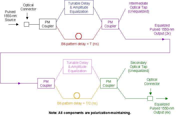
PriTel’s OCM uses Optical Time Domain Multiplexing to increase the input pulse rate. As shown in the schematic below, this is accomplished by dividing the input pulse into two separate legs of a Mach-Zehnder fiber interferometer.
One leg provides a variable pulse delay and amplitude equalization, and the other leg, a fixed bit-pattern delay. The two pulses are then recombined, interleaving them to produce a repetition rate of two times the input rate.

The OCM-4 unit has two cascaded stages of 2X. The OCM-8 and OCM-16 add additional stages of 2X and 4X to the OCM-4. As shown in the schematic, there is an intermediate optical tap, and the OCM-4 can be configured to provide 2X output pulses. This feature allows the researcher to align the experimental setup at lower rates. When the OCM is operating at 4X output, this 2X intermediate port has unequalized pulses with a reduced input extinction ratio.
For Bit Error Rate Testing with PRBS, the input data pattern is delayed by ½ the pattern length and then recombined to produce the same PRBS at twice the repetition rate. For the example of 27-1 bits at 10 GHz, the bit-pattern delay in the first stage of the OCM-4 is 6.4 ns, and 3.2 ns in the second stage. For researchers who use several different bit-pattern/pulse-rate combinations, kits are available enabling the user to reconfigure the OCM.
Return to previous page
